21+ 4 Bit Adder Truth Table
Can be constructed with full adders connected in cascaded see section 21 with the carry output. Youll get a detailed solution from a subject matter expert that helps you learn core concepts.
How To Make A Truth Table Of A 4 Bit Adder Circuit Quora
Arithmetic and Logic Unit ALU is made of Arithmetic and Logic Units.
. From each full adder connected to the carry input of the next full adder in the chain. Half Adder Circuit And Truth Table October 28 2020 by Electrical4U A Half Adder is defined as a basic four terminal digital device which adds two binary input bits. 8-bit and 16-bit Carry Look-ahead Adder circuits can be designed by cascading the 4-bit adder circuit with carry logic.
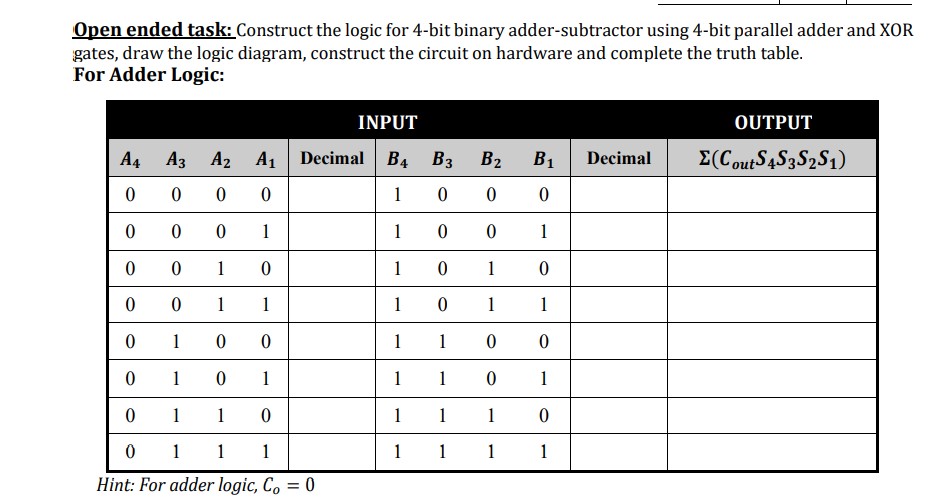
Draw the logic diagram. The adder adds the two inputs A and B in parallel producing the sum S. The digital systems handles the decimal number in the form of binary coded decimal numbers BCD.
If you need it very much you have to generate it. But I must warn you it is going to be large because there are so many. 4-bits of output and the bottom 4 multiplexers starting from the left are the last 4-bits of output.
23 Design of a 4-bit ALU using Proteus. 4-BIT BINARY FULL ADDER WITH FAST CARRY The SN5474LS283 is a high-speed 4-Bit Binary Full Adder with internal carry lookahead. Waveform Descriptions The waveform for the Full Adder shows that the circuit works because.
Here is a 4-bit adder truth table for reference. You are unlikely to find full truth table of a 4-bit adder circuit. This problem has been solved.
How many full and half adders are needed for 8-bit numbers. 1 Half Adder and 16 Full Adders will be required. Draw K-maps using the above truth table and determine the simplified Boolean expressions- Also Read-Full Subtractor.
For instance for a 4-bit adder four 1-bit full-adders are needed. BCD Adder Circuit BCD Adder Truth Table BCD Adder Block Diagram. So option C is correct.
This paper considers and designed sub-blocks such as Addersubtraction. What is half adder write its truth table. Assuming that A and B are stored in two input registers.
4 Bit Serial Adder Serial Adder performs the addition operation bit-by-bit therefore it requires only one full adder irrespective of number of bits to be addedThe serial adder requires simpler. It accepts two 4-bit binary words A1A4.

Let S Learn Computing 4 Bit Arithmetic Circuit
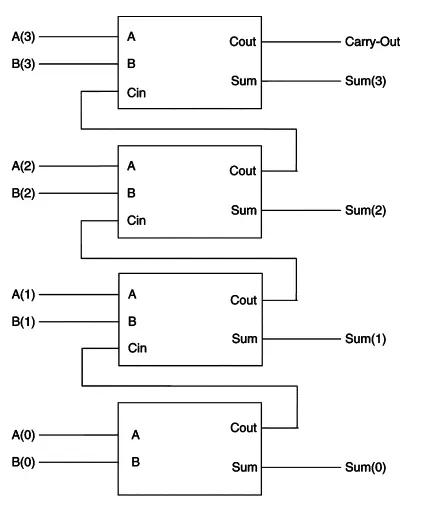
4 Bit Full Adder Using Logic Gates In Proteus The Engineering Projects
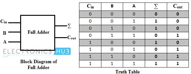
Binary Adder And Subtractor Circuits Half And Full Adder Subtractor
Ripple Carry Adder 4 Bit Ripple Carry Adder Circuit Propagation Delay

Table V From Design Of Adder Subtractor Circuits Based On Reversible Gates Semantic Scholar
Can Someone Draw A Circuit Diagram Of 4 Bit Carry Look Ahead Adder And Write A Brief Explanation Of The Adder Quora

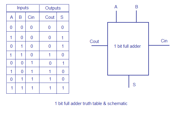
The Truth Table Of 1 Bit Full Adder Download Scientific Diagram
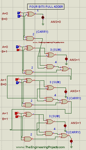
4 Bit Full Adder Using Logic Gates In Proteus The Engineering Projects

Cd4008 4 Bit Binary Full Adder
How To Make A Truth Table Of A 4 Bit Adder Circuit Quora
How To Make A Truth Table Of A 4 Bit Adder Circuit Quora

2 Bit Full Adder A Schematic Of An N Bit Full Adder Constructed From Download Scientific Diagram
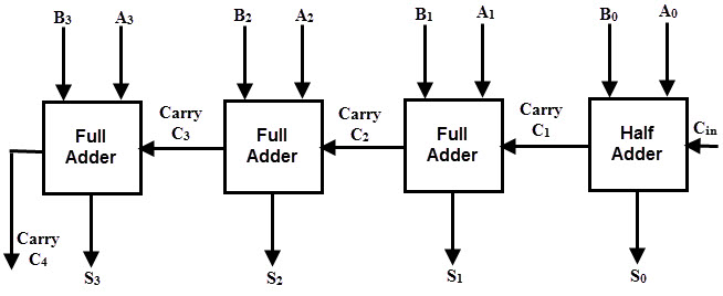
Binary Adder And Subtractor Circuits Half And Full Adder Subtractor

Would A 4 Bit Adder Based On A Lookup Table Be A Good Idea For A Fast Adder Quora

Truth Table For A Three Bit Adder Download Table
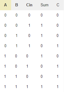
Parallel Adder 4 Bit Electronics Hub
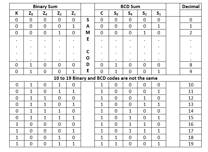
Decimal Or Bcd Adder Javatpoint